Posts

Showing posts from March, 2021

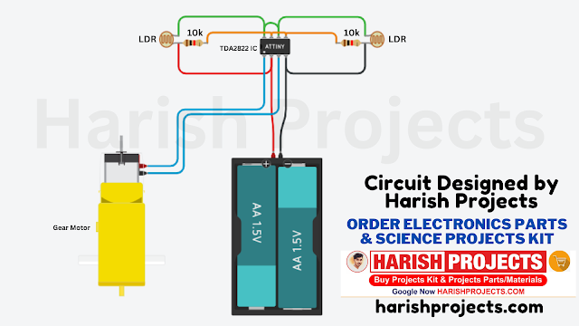
Sun Tracker Solar Panel - Circuit Diagram | Dual Axis Without Arduino | Harish Projects
Image
 Circuit Components List  1. TDA2822 IC 2x 2. 10k ohm Resistor 4x 3. 5mm LDR 4x 4. N20 Gear Motor 2x 5. N20 Wheel 6. Solar Panel  7. Zero PCB 8. Sunboard  9. 3.7v Small Battery  10. Charging Module 11. Tip Top Button Ordre all components from Here  Click here 👉  https://harishprojects.com/   …….. Circuit Diagram……….. ……….Watch full Detailed video………
क्या आप साइंस प्रोजेक्ट खरीदना चाहते है। वो अभी अपने idea का। तो ये सिर्फ आपके लिए हैं।

Image
 Click Here 👇👇👇 https://www.instagram.com/harishchoudhary70/

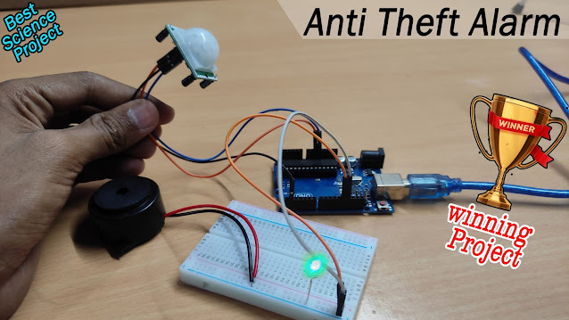
PIR motion Detection Anti Theft Prevention - Amazing Best winning science Project

Image
DIAGRAM ARDUINO CODE //MULTI PURPOSE VID instagram - harishchoudhary70  int led = 13;                // the pin that the LED is atteched to int sensor = 2;              // the pin that the sensor is atteched to int state = LOW;             // by default, no motion detected int val = 0;                 // variable to store the sensor status (value) void setup() {   pinMode(led, OUTPUT);      // initalize LED as an output   pinMode(sensor, INPUT);    // initialize sensor as an input   Serial.begin(9600);        // initialize serial } void loop(){   val = digitalRead(sensor);   // read sensor value   if (val == HIGH) {           // check if the sensor is HIGH     digitalWrite(led, HIGH);   // turn LED ON     delay(5000);                // delay 100 milliseconds           if (state == LOW) {       Serial.println("Motion detected!");        state = HIGH;       // update variable state to HIGH     }   }    else {       digitalWrite(led, LOW); // turn LED OFF       delay(100);     

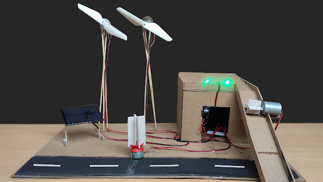
Best science Project Make Eco-friendly science Project 100% free Energy pt. 2

Image
              Video Link Click Here to watch https://youtu.be/J-QN4TQ8ijQ                             Circuit Diagram

Wireless Electricity Transfer - Best science Project

Image
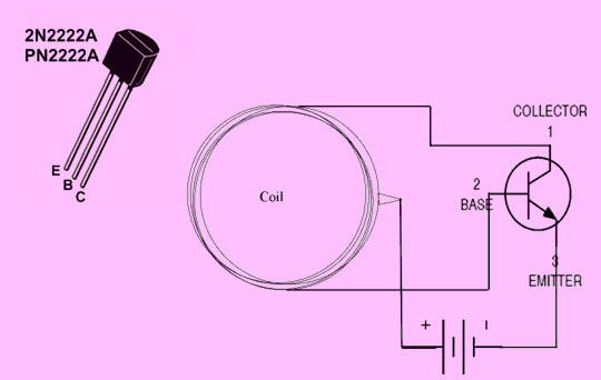
 Transmitter Take a Glass and whirl a wire on it 15 times after whirling a wire about three inches make a loop for center terminal and continue the process. Now take transistor BC547 or 2N2222 and connect its base terminal to one end of the copper coil, the collector terminal to the other end of the copper coil and now connect the emitter terminal to the negative (–ve) terminal of an 5v or 9v Power Adapter. The center terminal of the copper coil will be connected with the positive (+ve) terminal of an 5v or 9v Power Adapter. When then the receiver coil is placed 1 inch above the transmitter coil, then the LED will Glow. Receiver Make a 15 turn copper coil and connect a   Light to its ends. Wireless Power Transfer Circuit Working The wireless power transmission can be defined as the energy that can be transmitted from the transmitter to a receiver through an oscillating magnetic field.

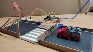
Accident Prevention Zebra crossing Gate Best winning science Project

Image
                            ........ Arduino Codes......... #include <Servo.h> //import library       Servo myservo;  int led = 13;   Servo myservo1;    int led1 = 12;                               void setup()  {       pinMode(led, OUTPUT);     myservo.attach(9, 500, 2500);      pinMode(led1, OUTPUT);   myservo1.attach(10, 500, 2500); }        void loop()  {        // Rotate Servo 3 by 180 degree   myservo.write(90);   myservo1.write(0);   delay(10);   digitalWrite(led, HIGH);      delay(8000);                 digitalWrite(led, LOW);        myservo.write(0);   myservo1.write(0);   delay(1000);    myservo.write(0);   myservo1.write(90);   delay(10);     digitalWrite(led1, HIGH);      delay(8000);                  digitalWrite(led1, LOW);       myservo.write(0);   myservo1.write(0);   delay(1000);                //    }

How to make Smart Traffic System science Project

Image
  Arduino Codes /*   Rotate Multiple Servo in Sequence : Code by   Kapil */ #include <Servo.h> Servo servo_6; Servo servo_9; Servo servo_10; Servo servo_11; void setup() {   servo_6.attach(6, 500, 2500);   servo_9.attach(9, 500, 2500);   servo_10.attach(10, 500, 2500);   servo_11.attach(11, 500, 2500); } void loop() {   // Rotate Servo 1 by 180 degree   servo_6.write(180);   servo_9.write(0);   servo_10.write(0);   servo_11.write(0);   delay(1000); // Wait for 1000 millisecond(s)   servo_6.write(0);   servo_9.write(0);   servo_10.write(0);   servo_11.write(0);   delay(1000); // Wait for 1000 millisecond(s)   // Rotate Servo 2 by 180 degree   servo_6.write(0);   servo_9.write(180);   servo_10.write(0);   servo_11.write(0);   delay(1000); // Wait for 1000 millisecond(s)   servo_6.write(0);   servo_9.write(0);   servo_10.write(0);   servo_11.write(0);   delay(1000); // Wait for 1000 millisecond(s)   // Rotate Servo 3 by 180 degree   servo_6.write(0);   servo_9.write(0);   servo_10.w