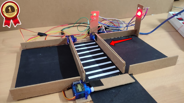
Dual Axis Mini CCTV Camera using ESP32 Cam | IOT Based Science Project / Harish Projects

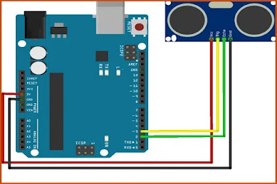
Purchase Course Video👇 https://harishprojects.graphy.com/ Watch full Detailed Video👇 Project Code👇 #include "esp_camera.h" #include <Arduino.h> #include <WiFi.h> #include <AsyncTCP.h> #include <ESPAsyncWebServer.h> #include <iostream> #include <sstream> #include <ESP32Servo.h> #define PAN_PIN 14 #define TILT_PIN 15 Servo panServo; Servo tiltServo; struct MOTOR_PINS { int pinEn; int pinIN1; int pinIN2; } ; std::vector<MOTOR_PINS> motorPins = { { 2 , 12 , 13 } , //RIGHT_MOTOR Pins (EnA, IN1, IN2) { 2 , 1 , 3 } , //LEFT_MOTOR Pins (EnB, IN3, IN4) } ; #define LIGHT_PIN 4 #define UP 1 #define DOWN 2 #define LEFT 3 #define RIGHT 4 #define STOP 0 #define RIGHT_MOTOR 0 #define LEFT_MOTOR 1 #define FORWARD 1 #define BACKWARD - 1 const int PWMFreq = 1000 ; /* 1 KHz */ const int PWMResolution = 8 ; const int PWMSpeedChannel = 2 ;...