Hello Guy's welcome to my website "Harish Projects" my name is "HARISH CHOUDHARY"
In this website you will get ideas for making new science projects, Technology And I keep uploading videos of science projects in my YouTube channel "Harish Projects''
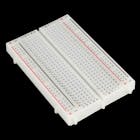
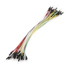
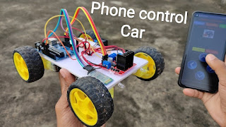
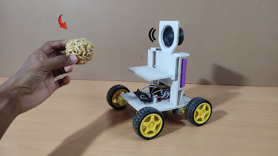
This is just a simple robot arm made out of readily available materials and instruments, such as micro servos, cardboard, and hot glue, designed for beginners. The code and circuit can be improved, so feel free to make changes and learn!
Features
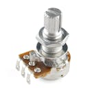
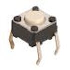
It can record and play five positions using potentiometers and buttons. (But you can add as many as you want).
Making video.
//Arduino Code//
//Code written by Ryan Chan; it is pretty inefficient, but gets the job done, I challenge you to make it more efficient!//*IMPORTANT CHANGES IN VERSION 2: LEDs 4 and 5 have been moved to pins 7 and 8 respectively; Buttons 1 and 2 have been moved to pins 12 and 13 respectively. This is to make wiring easier.#include<Servo.h>Servoservo1;//ServosServoservo2;Servoservo3;constintLED1=2;//LEDsconstintLED2=3;constintLED3=4;constintLED4=7;constintLED5=8;constintbutton1=12;//Buttonsconstintbutton2=13;intbutton1Presses=0;//Button valuesbooleanbutton2Pressed=false;constintpot1=A0;//Potentimetersconstintpot2=A1;constintpot3=A2;intpot1Val;//Potentimeter valuesintpot2Val;intpot3Val;intpot1Angle;intpot2Angle;intpot3Angle;intservo1PosSaves[]={1,1,1,1,1};//position savesintservo2PosSaves[]={1,1,1,1,1};intservo3PosSaves[]={1,1,1,1,1};voidsetup(){servo1.attach(5);// Set up everything and will run once; attach servos and define the pin modesservo2.attach(6);servo3.attach(9);pinMode(LED1,OUTPUT);pinMode(LED2,OUTPUT);pinMode(LED3,OUTPUT);pinMode(LED4,OUTPUT);pinMode(LED5,OUTPUT);pinMode(button1,INPUT);pinMode(button2,INPUT);Serial.begin(9600);}voidloop(){// put your main code here, to run repeatedly: pot1Val=analogRead(pot1);// This will read the values from the potentimeters and store it...pot1Angle=map(pot1Val,0,1023,0,179);// ... and this will map the values from the potentiometers to values the servos can use and store it for later usepot2Val=analogRead(pot2);pot2Angle=map(pot2Val,0,1023,0,179);pot3Val=analogRead(pot3);pot3Angle=map(pot3Val,0,1023,0,179);servo1.write(pot1Angle);// These will make the servos move to the mapped anglesservo2.write(pot2Angle);servo3.write(pot3Angle);if(digitalRead(button1)==HIGH){// This will check how many times button1 is pressed and save the positions to an array depending on how many times it is pressed; switch/case works like a if statementbutton1Presses++;switch(button1Presses){case1:servo1PosSaves[0]=pot1Angle;servo2PosSaves[0]=pot2Angle;servo3PosSaves[0]=pot3Angle;digitalWrite(LED1,HIGH);Serial.println("Pos 1 Saved");break;case2:servo1PosSaves[1]=pot1Angle;servo2PosSaves[1]=pot2Angle;servo3PosSaves[1]=pot3Angle;digitalWrite(LED2,HIGH);Serial.println("Pos 2 Saved");break;case3:servo1PosSaves[2]=pot1Angle;servo2PosSaves[2]=pot2Angle;servo3PosSaves[2]=pot3Angle;digitalWrite(LED3,HIGH);Serial.println("Pos 3 Saved");break;case4:servo1PosSaves[3]=pot1Angle;servo2PosSaves[3]=pot2Angle;servo3PosSaves[3]=pot3Angle;digitalWrite(LED4,HIGH);Serial.println("Pos 4 Saved");break;case5:servo1PosSaves[4]=pot1Angle;servo2PosSaves[4]=pot2Angle;servo3PosSaves[4]=pot3Angle;digitalWrite(LED5,HIGH);Serial.println("Pos 5 Saved");break;}}if(digitalRead(button2)==HIGH){// Pretty self-explnatory herebutton2Pressed=true;}if(button2Pressed){// if the boolean button2Press is true, then the servos will run though all their saved positionsfor(inti=0;i<5;i++){servo1.write(servo1PosSaves[i]);servo2.write(servo2PosSaves[i]);servo3.write(servo3PosSaves[i]);Serial.println(" potentimeter Angles: ");Serial.println(servo1PosSaves[i]);Serial.println(servo2PosSaves[i]);Serial.println(servo3PosSaves[i]);delay(1050);}}delay(300);} //Projects Diagram//


_ztBMuBhMHo.jpg?auto=compress%2Cformat&w=140&h=140&fit=fill&bg=ffffff)
.png)
Comments